
flow sheet diagram of glass industry manufacturer Grasping strong production capability, advanced research strength and excellent service, Shanghai flow sheet diagram of glass industry supplier create the value and bring values to all of customers.
 WhatsApp)
Oil Industry Process Flow Diagram. Edit this example. Oil Sands Process Flow Diagram. Edit this example. Water Recycling Process Flow Diagram. Edit this example. Wind Energy Process Flow Diagram. Edit this example. Drinking Water Treatment Process Flow Diagram. Edit this example.
May 31, 2014· Glass industry presentation 1. Glass Industry Presented to: Ma'am Aasia Farrukh Presented By: Faheem Abbas (22) Saeed Akhter (23) Rafique Khan (03) Muhammad Zubair (19) Muhammad Mohsin (39) Abbas Khattak (40) Syed Imad Zakir (56) 28/05/2k14 1 Wah Engineering College, Wah Cantt.

Process flow diagrams (PFDs) are used in chemical and process engineering. These diagrams show the flow of chemicals and the equipment involved in the process. Generally, a Process Flow Diagram shows only the major equipment and doesn't show details. PFDs are used for visitor information and new employee training.
A process flow diagram (PFD) is a diagram commonly used in chemical and process engineering to indicate the general flow of plant processes and equipment. The PFD displays the relationship between major equipment of a plant facility and does not show minor details such as piping details and designations. Another commonly used term for a PFD is a flowsheet
Float glass is a sheet of glass made by floating molten glass on a bed of molten metal, typically tin, although lead and various low melting point alloys were used in the past. This method gives the sheet uniform thickness and very flat surfaces. Modern windows are made from float glass.
The glass is made to move through the annealing lehr where such internal stresses are removed, as the glass is cooled gradually, to make the glass more prone to cutting. Stage 5 - Inspection: To ensure the highest quality, glass manufacturers carry out inspection at every stage.
A LIST OF ENGINEERING PROCESS FLOW DIAGRAMS AND PROCESS DATA SHEETS A-1 PROCESS FLOW DIAGRAMS USING VISIO 2002 SOFTWARE Figure 1-12b Process flow diagram (Feed and fuel desulfurization section). Figure 1-12c Typical process flow diagram for the production of Methyl Tertiary Butyl Ether (MTBE). Figure 1-14 Piping and instrumentation diagram for ...
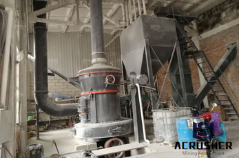
manufacture of such glass is in four phases: (1) preparation of raw material, (2) melting in a furnace, (3) forming and (4) finishing. Figure 11.15-1 is a diagram for typical glass manufacturing. The products of this industry are flat glass, container glass, and pressed and blown glass. The
Chapters 1 and 2 provide general information on the glass industry and on the industrial processes and techniques used within this sector. Chapter 3 provides data and information concerning the environmental performance of installations within the sector, and in operation at the timeof writing, in terms of current ...
contain glass production processes (as defined below) and that emit 25,000 metric tons or more of GHGs per year (expressed as carbon dioxide equivalents) from glass production processes, stationary combustion, miscellaneous use of carbonates, and other source categories (see information sheet on
WhatsApp)