
modeling ball end mill in solidworks manufacturer Grasping strong production capability, advanced research strength and excellent service, Shanghai modeling ball end mill in solidworks supplier create the value and bring values to all of customers.
 WhatsApp)
Nov 21, 2008· Re: Ball End Mill Sweep Yes you need to do a straight sweep first, then revolve (cut) at the end of the sweep to get the rounded end, then another sweep perpendicular into the center of the revolve. So 2 straight sweeps and 1 revolve to make a right angle.
Modeling Ball End Mill In Solidworks . Ball end mill feature modeling | SOLIDWORKS Forums. Then, model a solid body that would represent the ball end mill at the end of the path.Solidworks says that a corner rounding tool won't work, if you first make the cut with the a chamfer mill, then change the profile to corner rounding, it will work.
Ball end mill feature modeling | SOLIDWORKS Forums. Then, model a solid body that would represent the ball end mill at the end of the path.Solidworks says that a corner rounding tool won't work, if you first make the cut with the a chamfer mill, then change the profile to corner rounding, it will work.

Jul 30, 2017· Making helical flutes on a special solid carbide end mill in SolidWorks 2016 Disclaimer - The flute shape and cutter geometry is an approximation and does not .

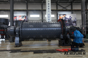
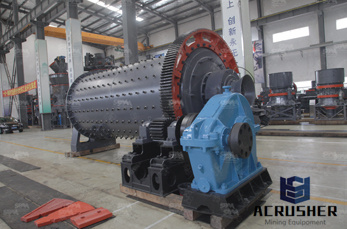
3D model ball mill . Ball Mills are generally used to grind material 1/4 inch and finer, down to the particle size of 20 to 75 microns. To achieve a reasonable efficiency with ball mills, they must be operated in a closed system, with oversize material continuously being recirculated back into the mill .
Tutorial Solidworks Grinding Mill. Gypsum mill for all requirements gypsum plaster manufacturing process gypsum mill for all requirements endmill solidworks 3d cad model grabcad modeling ball end mill in solidworks grinder milling solidworks chollet ball mill solidworks make crusher solidwork design drawing mill solidworks mastercam x5 mill tutorial pdf
Ball nose cutters are similar to slot drills, but the end of the cutters are hemispherical. They are ideal for machining 3-dimensional contoured shapes in machining centres, for example in moulds and dies. used for creating radius profile in dies

Web Help Content Version: SOLIDWORKS 2019 SP04 To disable Web help from within SOLIDWORKS and use local help instead, click Help > Use SOLIDWORKS Web Help. To report problems encountered with the Web help interface and search, contact your local support representative.
Jun 06, 2014· A ball mill is an endmill with the corner radius being the same as the radius of the endmill. What you had revolved was more of a port cutter which won't work. Some profiles that Solidworks says won't work, actually will with a little work around.

Modeling Ball End Mill Channel on Curved Surface I'm trying to make a fairly unusual part, and I've been able to solve most of the issues with the standard Google-fu, but I've hit a road-block on this one. I'm trying to fabricate a flask-holder which can both heat and cool a standard round-bottom flask, with a nominal radius of 1.688". ...
Ball Mill Solidworks 3x. modeling ball end mill in solidworks. modeling ball end mill in solidworks - paver. Ball end mill feature modeling | SOLIDWORKS Forums Then, model a solid body that would represent the ball end mill at the end of the pathSolidworks says that a corner rounding tool won't work, if you first make the cut with the a .

Sep 29, 2012· Video Tutorial on Modeling Milling Tool Cutter in SolidWorks. Video Tutorial on Modeling Milling Tool Cutter in SolidWorks. ... Making Helical Flutes in SolidWorks 2016 - Special Form End Mill ...
how to make end mill cutter in solidworks. vikash. 30 Aug, 2013 02:52 PM end mill cutter with variable cutting angle. end-mill-with-variable-cutting-angle-1.snapshot.2_(1).zip. ... How to model an end mill using Solidworks? 0 answers 35 views 0 followers How can I model a rotary die cutter in SolidWorks.
Looking for downloadable 3D models, designs, and CAD files? Join the GrabCAD Community to get access to 2.5 million free CAD files from the largest collection of professional designers, engineers, manufacturers, and students on the planet.

2018119with a 116 ball end mill the post that forms the hole in the cutting board must have a draft of 5 and will be made with a 5 tapered end mill of 25 diameter 4 create a 3d model for the cutting board in solidworks refer to 3 for.

Looking for downloadable 3D models, designs, and CAD files? Join the GrabCAD Community to get access to 2.5 million free CAD files from the largest collection of professional designers, engineers, manufacturers, and students on the planet.
Sep 27, 2016· Learn how an End Mill is made using SolidWorks. Learn how an End Mill is made using SolidWorks. Skip navigation ... Modeling of the spiral drill in SolidWorks - Duration: 33:36.
For example, for a flat-end milled volume feature, right-click the volume feature, and click Processing > Tooling > Ball End Mill. Search 'Volume Features' in the SOLIDWORKS Knowledge Base. Provide feedback on this topic
tutorial solidworks grinding mill - swanlakeorgin. ball mill solidworks End Mills - HSMWorks- ball mill solidworks,Flat nose mills are used for milling 2D contours and pockets Ball nose mills are used for 3D milling Bull nose end mills have a radius corner They are used to create a fillet on the bottom of a wall Because they are . [Chat Online]
Jul 12, 2007· I made a 1/2" end mill model last year while teaching a tool grinder how to use SWX. Extrude the shank first, then drew a profile centered on the shank of a single flute combined with its "core" diameter. The core diameter I would describe as smallest cross section between the flutes which I simply transferred into a circle.
Oct 22, 2019· End Mill Model I'm trying to model a 15° center cut end mill, but I can't figure out how to draw the flutes accurately. ... How to draw ball end mill cutout? By derf in forum Solid Edge Forum Replies: 1 Last Post: July 31st, 2009, 06:39 AM. solidworks end mill ? By RAL in forum SolidWorks Forum Replies: 1 Last Post: July 12th, 2007, 05:16 PM ...
I've been trying to model cut produced by a ball end mill taking an arbitrary 3D path. I know how to do this for 2D paths (and this has been discussed a couple of times on this forum), but I have had little to no success extending this to paths in 3D. I've attached an Inventor file that demonstrates ...
Oct 23, 2014· Hi, One of my products has a complicated cut and I can never figure out the correct way to model this in 3 dimensions. I've attached a section of the 2D drawing that shows this cut along with an actual picture of what it looks like.
three-dimensional model mill. The Computer-Aided Design ("CAD") files and all associated content posted to this website are created, uploaded, managed and owned by third party users.
WhatsApp)