
fluid power milling machine diagram manufacturer Grasping strong production capability, advanced research strength and excellent service, Shanghai fluid power milling machine diagram supplier create the value and bring values to all of customers.
 WhatsApp)
Aug 15, 2017· I was trying to understand the schematic of an hydraulic power unit operated by a bidirectional electric motor. Depending on the direction of rotation of the motor, fluid would flow out one port in the other but when the motor stopped no fluid would .
Apr 21, 2018· Milling is the machining process in which the removal of metal takes place due to the cutting action of a rotating milling cutter.. In a milling machine, the cutter is rotating due to this workpiece is fed against it.This can hold more than one tool at a time. The cutter rotates at a high speed and because of the many cutting edges, it removes metal at a very fast rate.
Energy / Power Plants ; Fluid milling machine . Energy requirements evaluation of milling machines based on . It was assumed that the additional load loss is a constant for small milling machine. This part of energy consumption only exists in the normal cutting fluid).
Dura-Bar 65-45-12 is a continuous cast iron bar stock. It machines easily and provides excellent surface finishes. It also features good impact, tensile, and yield strengths, along with good fatigue resistance. This alloy sees use in automotive, fluid power, power transmission, pump/compressor applications, and .
A hydraulic drive system is a quasi-hydrostatic drive or transmission system that uses pressurized hydraulic fluid to power hydraulic machinery.The term hydrostatic refers to the transfer of energy from pressure differences, not from the kinetic energy of the flow.. A hydraulic drive system consists of three parts: The generator (e.g. a hydraulic pump), driven by an electric motor or a ...
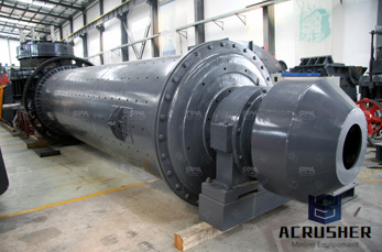
fluid power milling machine diagram. ball mill schematic diagramsmegakebap. Ball mill Wikipedia. A ball mill a type of grinder is a cylindrical dev used in grinding (or mixing) materials like ores chemicals ceramic raw materials and paints.Ball . Chat Online
cluster mill diagram. This post describe about Cutting Fluid,properties of cutting fluids,function of cutting fluid and types of cutting fluids.
Mar 22, 2019 - A family of graphic symbols has been developed to represent fluid power components and systems on schematic drawings. In the United States, the American National Standards Institute (ANSI) is responsible for symbol information. The Institute controls ...
a diagram of a crushing machine a diagram of a crushing machine. Grinding Equipment Product Center. LM Vertical Grinding Mills. It has appliion in metallurgy, construction, and mining Chat Now; primary grinding circuit Mining, Crushing, Milling Posts Related to schematic diagram of the primary crusher machine. Circuit Diagram

Dec 09, 2016· A milling machine which has a ram on the top of the column is called ram type milling machine. Generally ram is used in vertical milling machine. It can be moved on the column in transverse direction (i.e. in and out when operated from the knee side). 5. Manufacturing or Bed -Type Milling Machine 6. Planer-Type Milling Machine:
Variable volume pumps (4–70 gpm), piston pumps to 4,000 psi, directional, electro-proportional, pressure- and flow-control valves, and standard and custom hydraulic power units. Daman Products Standard and custom hydraulic valve manifolds and sub plates. Delta Power Gear pumps, 0.5–34 gpm gear motors, cartridge valves, manifolds and power units
Fluid power diagrams: read and interpret system-layout and circuit diagrams e.g. use of ISO 1219-2 Part 2, component lists, component data sheets, displacement-step diagrams, operating instructions, installation and maintenance manuals; applications e.g. logic, memory and multi-actuator sequential
BUILDING MFP SEALS FOR YOU: Manufacturing: CNC Machining • Injection & Compression Molding • Rubber to Metal Bonding • Transfer Molding Services: Blanket Orders • JIT Inventory • KanBan Quality: PPAP Submission • Certification of Materials • Non-Contact Vision System (0.4 µm) • ANSI / ISO / ASQ - Q9001-2015 Certified. MFP Seals, a division of Martin Fluid Power, is focused on ...

Reading Fluid Power Diagrams. Using the symbology previously discussed, a fluid power diagram can now be read. But before reading some complex examples, let's look at a simple hydraulic system and convert it into a fluid power diagram. Using the drawing in Figure 27, the left portion of Figure 28 lists each part and its fluid power symbol.
Hydraulics (from Greek: Υδραυλική) is a technology and applied science using engineering, chemistry, and other sciences involving the mechanical properties and use of liquids.At a very basic level, hydraulics is the liquid counterpart of pneumatics, which concerns gases. Fluid mechanics provides the theoretical foundation for hydraulics, which focuses on the applied engineering using ...
In this machine, a multipoint cutter is rotating against the workpiece and material removed from the workpiece accordingly.. In today's article, you will learn about the definition, parts, types, and operation of a milling machine, also at the end of the article, I will add the downloadable link of the PDF.. Milling Machine Definition. The milling machine is defined as perhaps most widely ...
hydraulic circuit diagram for shaper machine. hydraulic milling circuit diagram - SCM Page 189 of 341 circuits for Milling machine,, hydraulic circuit diagram for shaper machine. ... Standard symbols allow fluid power schematic diagrams to be read and, Read more about hydraulic symbology in a, CHAPTER 4: ISO Symbols and.
Mar 26, 2019 - Explore A's board "Hydraulics" on Pinterest. See more ideas about Hydraulic systems, Schematic drawing, Electrical diagram.
Diagram Of Hydraulic System In Crusher. Cone crusher hydraulic system diagram - mtm crusher in, crushers jobs in south africa careerjetcoza fitter plant cone crusher construction company has the need for a crusher and hydraulic mechanic with at least 10 aeration systems, piping installations, pressure vessels ontact supplier.
In this unit you will be learning about Fluid Power Schematic Diagram and at the end you should be able to describe the purpose of Schematic Diagram, you should be able to identify the components on a diagram, and you should be able to use a Schematic to understand how hydraulic circuits work.
Fluid Power Educational Foundation, 3333 North Mayfair Rd., Milwauke e, WI 53222 -3219 ... machine, is to perform work. The accomplishment of work requires the application of kinetic energy to a resisting object resulting in the object moving through a distance. In a pneumatic system, energy is stored in a potential state under the form

Power milling machine diagram andponents grinding mill equipment. power milling machine diagram and components milling machines a milling machine is a power driven milling machining wikipedia some horiontal milling machines are equipped with a power-take-off voronoi diagram asme has developed the standards b5.45-1972 milling machines and b94.
Hydraulic machines use liquid fluid power to perform work. Heavy construction vehicles are a common example. In this type of machine, hydraulic fluid is pumped to various hydraulic motors and hydraulic cylinders throughout the machine and becomes pressurized according to the resistance present. The fluid is controlled directly or automatically by control valves and distributed through hoses ...
A fluid or milling gas, usually air or inert gas is injected as a high-pressure jet through nozzles at the bottom of the loop. The powder particles in the mill are accelerated to high velocity. The kinetic energy of the air plus the turbulence created causes interparticle .
WhatsApp)